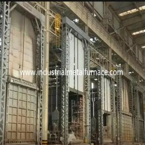
Gas Fired Industrial Car Bottom Furnace ,
Bogie Hearth Furnace 7200×2200×1800mm
1. Application
The gas fired bogie hearth furnace is mainly used for heat
treatment of metal parts.
2.Structural Introduction
2.1 furnace body
The bogie hearth furnace for sale body steel structure is made from
12# -18# channel steel and 4-14mm steel plates. The side pillar and back
pillars are made from sectional steel, and are reinforced with sectional steel
bracings. The external wall of the furnace is painted with 2 layers of primers,
and 2 layers of coating paint. The key part of the furnace is painted with
heat resistant paint.
2.2 lining
The lining material is 1100℃ 1360type high aluminum refractory fibre
compacted block. This refractory lining structure has the advantages of low
heat conductivity, strong anti-shock capacity, and anti-erosion. Aluminum
silicate fiber compression block with thickness of 350mm is designed as
the high temperature refractory layer.
The total thickness of the furnace lining is 325mm. The lining adopts
composite large module structure and stainless steel round steel fixation technology.
The lining at high temperature section adopts aluminum silicate fiber
compression block, the thickness is 300mm.
2.3 bogie
The bogie hearth furnace design is comprised of heat preservation material,
bogie frame and moving mechanism. The refractory layer is divided into 3 sub-layers,
i.e., 1st top high-alumina brick layer, and 2nd and 3rd layer with both light clay bricks.
The bogie framework is made of 20# I-steel beam and 20# I-steel beam. The edges
of the bogie are made of 20# channel steel. The bogie is equipped with 10pieces of
wheels. Each wheel diameter is 350mm.
The car bottom furnace price is driven by motor reducer gear driving mechanism.
The moving speed of the bogie is 6-8m/min.
2.4 Sealing System
The sealing between the door and the body of the furnace and the trolley is
more critical.
The sealing of furnace door, furnace body and trolley is the key. The sealing between
the furnace door and the furnace body uses the electric push rod to press the closed
furnace door on the furnace door frame and the end face of the trolley. In this way,
the whole furnace door is tightly sealed, so as to ensure that the hot gas in the furnace
does not leak out from the furnace door.
2.5 furnace door
The furnace door is comprised of all-fiber lining and steel structure shell. The
door is built with silicate aluminum compressed fiber blocks same as that for the
furnace body. The shell is a welding structure from sectional steel and steel plates.
The furnace door has the feature of simple, practical, reliable and convenient
maintenance. The furnace door is fixed on the bogie.
Driving mode of furnace door: electric hoist is used to move up and down vertically.
A soft hard contact sealing structure is arranged between the furnace door and the
lining. When the furnace door is closed, the electric push rod mechanism is used to
compress the furnace door to make the sealing fiber block contact with the furnace
mouth for sealing. When the furnace door is opened, the gap between the furnace
door and the steel plate of the furnace mouth frame is 100 mm by pulling the electric
push rod pressing mechanism, so as to ensure that the furnace door does not scratch
or touch the relevant parts of the furnace lining and trolley during the lifting process.
And ensure smooth movement when opening and closing.
2.6 burning system
The burning system is comprised of Krom technology high speed burners, proportional
combustion control system, gas valve, solenoid valve, burner control box, etc. The
burner has the functions of automatic ignition, flame detection, and flame out alarm.
The burner controller receives the control signal of the temperature controller and
controls the large/small fire status of the burner based on the heat load requirement
so that adjustment of the temperature is realized.
A) The burner has adjustment function and the adjustment rate is 1:10 and the air
efficient is 1-5. The burner could meet the temperature uniformity of the heat
treatment process and effectively control the air-gas ratio so that the fuel consumption
is reduced.
B) When the furnace is working, the burning system could automatically cut off the
electrical gas valve and general safety valve in the case of power failure detected
by the alarm system. When the power supply is resumed, the worker needs to open
the safety valve and restart the ignition program after purging function is confirmed.
The burner is set with a proportional control unit which enables alternative burning
of large and small fire, fire out alarm, and re-ignition. The burner control box has both
manual and self-run modes available. The worker could operate in front of the
furnace or in the control cabinet.
C) The pipe before the burner is equipped with solenoid valve, and manual gas
adjustment valve. The valve system could realize an ideal gas/air supply ratio
so that the air excess efficient is lower than 1.1.
2.6.1 air system
The air piping system is comprised of high pressure centrifugal fan, automatic
regulation valve, pressure gauge and pipes. The air volume is to match the gas
volume, and the air excess rate is lower than 1.20.
2.6.2 gas supply system
The general gas supply pipe is equipped with a pressure regulation device
(equipped with a filter), a low pressure switch and a pressure gauge. For the sake
of safety there is one fast cut-off valve on the general gas pipe.
2.6.3 discharge system
The heat treatment furnace trolley takes direct fume discharge method. The fume
is directly vented out through the flue pipe to the atmosphere. The fume conducts
heat exchange with the heat exchange before emission to the atmosphere.
2.6.4 Furnace pressure control system
The pressure on the working table in the furnace is kept at (+15 Pa), which is
very beneficial to the uniformity of temperature and the thermal efficiency of the
furnace. When the pressure in the furnace is too high, the hot air in the furnace will
escape from the furnace mouth and other unsealed places, resulting in the heat loss
caused by the escape of the flue gas; because the high temperature flue gas in the
furnace escapes to the outside of the furnace, it will affect the door, the side seal
and burner of the furnace directly, which is related to the overall service life of the
furnace; when the pressure in the furnace is too low, a large number of cold air
outside the furnace will be absorbed into the furnace, as well. The heat loss of
off-furnace flue gas is increased. The low pressure of the furnace causes the
diffusion of cold air outside the furnace into the furnace, and secondary combustion
is formed due to the entry of oxygen-containing cold air, which has adverse effects
on the uniformity of furnace temperature, oxidation of workpiece and thermal
efficiency of the furnace. Therefore, effective technical measures must be taken to
control the furnace pressure with full automatic control. Our method is to control the
furnace pressure effectively by using a system consisting of pressure taking device,
pressure transmitter, intelligent instrument and so on. The furnace pressure is controlled
in the optimum state (the surface of the trolley is in a slightly positive pressure). At this
time, the exhaust gas is in a dynamic equilibrium state, which can not only ensure that
the furnace gas does not overflow, but also ensure that the cold air outside the furnace
is not sucked into the furnace, so as to save energy and maximize the efficiency
of the furnace.
2.6.5 Heat exchange and flue system
A flue is set at the back of the furnace, and it is carried out with the heat exchanger
(according to the national standard GB3486-83). The flue leads to the outside of the
factory building. The cold air is exchanged with the heat exchanger to preheat the
combustion-supporting air before entering the burner, so as to improve the heat
efficiency of the furnace.
Heat exchangers and flue gas exhaust pipes are insulated by internal insulation
(using fiber castables) to ensure the service life of heat exchangers and flues.
2.6.6 fault detection and alarm system
The furnace has a complete fault detection, alarm, diagnosis, and safety protection
system. On the control cabinet there is an alarm lamp.
2.7 control system
control system has the following parts: Ⅰ. Burning control system; Ⅱ. Electrical
power control system; Ⅲ.temperature control system .
Measures taken for burning control system:
K type thermal couple gets mV signal and sends it to temperature PID controller
(SHIMADEN brand). The temperature controller calculates the signal and outputs
4-20mADC control signal to the electrical actuator. The actuator further sends a
signal to the burner controller after calculation.
The burner controller is mainly responsible for ignition and flame detection.
When the terminal receives the ignition signal, the burner controller carries out
flame simulation and self testing stage. If during this simulation and self-test stage
the burner couldn’t detect the flame signal. The burner controller would open the
gas solenoid valve and convert the voltage 220VAC to 5KV for ignition (ignition
time about 3S). If the burner detects the flame signal in the safe time period (about
8S), the yellow indication light of the burner would be on (ignition successful). If the
burner couldn’t detect the flame signal, the red light would be on (ignition failed).
The burner controller is locked and the gas solenoid valve is cut off.
B) electrical power control system: The electrical power control system mainly
controls ON/OFF of the fan, and IN/OUT of the bogie.
C) temperature control and record system
The system has the functions of temperature setup, control and digital display.
And also there is an audible and visual alarm at over-temperature situations.
Temperature control zone arrangement
A:temperature control system
The furnace is equipped with 4 thermal couple and an intelligent temperature
controller. The furnace is controlled by 4 zones.
B: instrument temperature control
The temperature controller allows setup of heating time, holding time, and cooling
time. It has self-tuning and self-adjustment function, and displays SV and PV.
3. Main Technical Parameters
| No. |
Item |
Technical Parameters |
| 1 |
Furnace hearth effective working size |
7200*2200*1800mm
(excluding the height of support iron)
|
|
2
|
Furnace hearth size |
7600*2600*2300mm
(including the height of support iron)
|
| 3 |
Bogie loading capacity |
≤20ton |
| 4 |
Max working temperature |
1050℃ |
| 5 |
Furnace body surface temperature |
≤45℃+room temperature |
| 6 |
Max temperature rise speed |
200℃/hour at full loading capacity |
| 7 |
Temperature measurement accuracy |
≤±1℃ |
| 8 |
Temperature uniformity |
≤±10℃ |
| 9 |
Heating zone |
4 zones |
| 10 |
Fuel |
Natural gas |
| 11 |
fuel gases calorific value
Gas pressure before furnace
|
8600kcal/m3
20-70Kpa
|
| 12 |
Temperature control method |
Shimaden Intelligence temperature controller,
10 inch touch screen+Siemens PLC and manual control;
|
| 13 |
Temperature record |
K type thermocouple in the furnace hearth |
| 14 |
Hot air pipe surface temperature rise |
≤30℃ |
| 15 |
Bogie moving speed |
6-8m/min, with manual operate remote control |
| 16 |
Furnace door sealing method |
By electric push rod, 4 sets |
| 17 |
Furnace door opening method |
Electric up and down , speed 6-8m/min, with manual operate remote control |
| 18 |
Furnace lining |
heat resistant all fiber structure |
| 19 |
Gas burner |
AGS100HB burner, 230KW/h, 8pcs
(German technology)
|
| 20 |
Consumption index |
Heat efficiency at full load η≥40% |
| 21 |
Furnace door surface temperature |
≤50℃+ room temperature |
| 22 |
Full power gas consumption |
136Nm3/h |
| 23 |
Gas pipe line demand |
185Nm3/h |
| 24 |
Air consumption |
2392Nm3/h |
| 25 |
Bogie motor power |
7.5KW*1 set |
| 26 |
Combustion fan power |
7.5KW |
| 27 |
Bogie transmission method |
Motor reducer sprocket drive
Bogie wheel moving method: remote control
|
| 28 |
Sealing between bogie and side wall |
Electric push rod, 4sets |
| 29 |
Sealing between bogie and back wall |
By spring fiber blocks |